This information is taken from Workshop Manual TSD2476, Section G. We advise only undertaking work on the hydraulic system if you have read and can refer to TSD2476.
Introduction
It is essential that, in order to obtain optimum performance, the hydraulic systems must at all times be completely free from air. The two hydraulic systems are recirculatory and therefore, if air is allowed to enter them at any point, it could cause reduced efficiency.
Please note that this is a two stage process - these cars have a low pressure (master cylinder) system and a high pressure (power brake) system
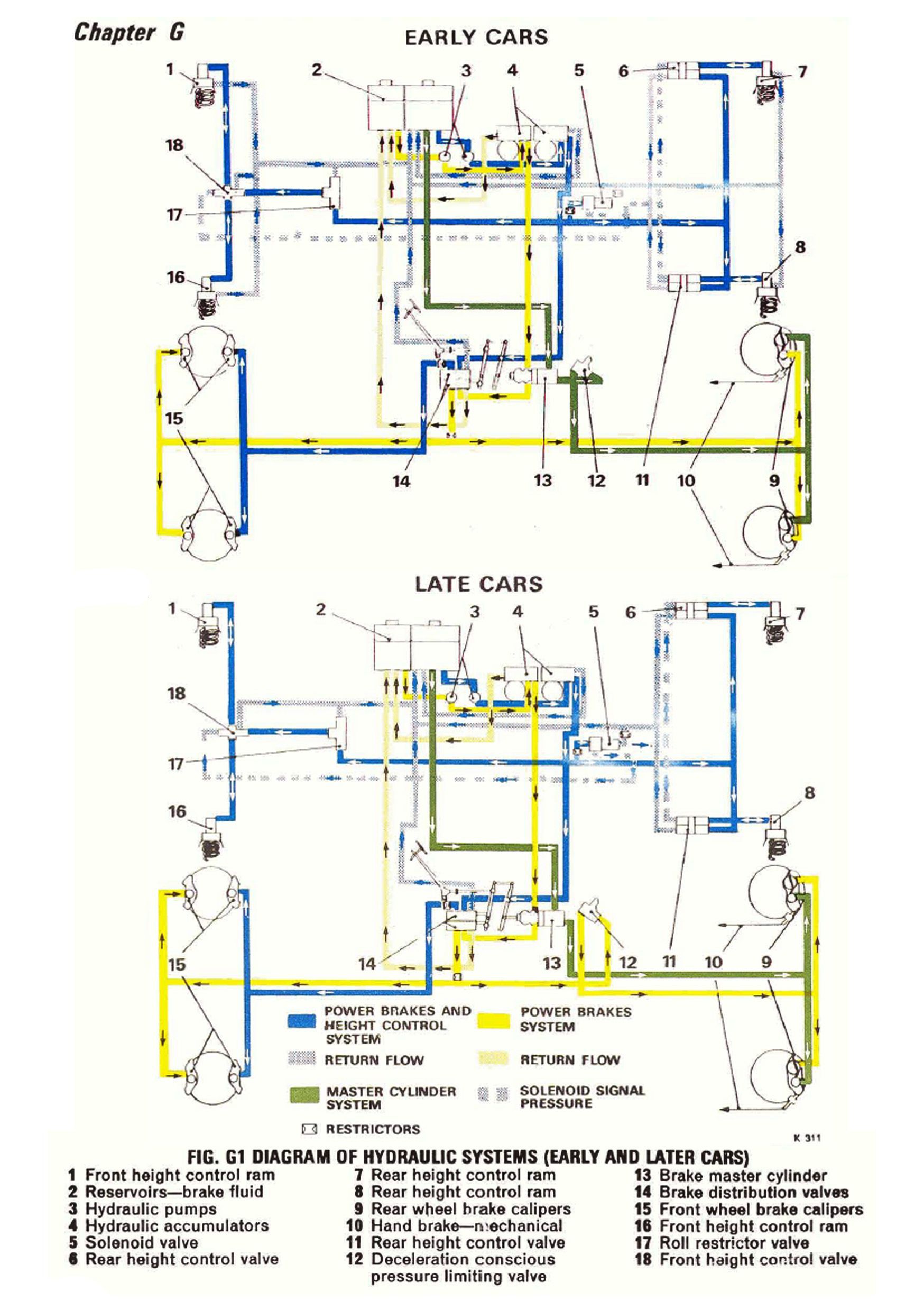
The front hydraulic reservoir supplies fluid for the front brake pump, the front hydraulic accumulator, the lower brake distribution valve, the front calipers of the front brakes and the power brake cylinders of the rear brake calipers.
The rear hydraulic reservoir supplies the rear brake pump, the rear hydraulic accumulator, the automatic height control system, the upper brake distribution valve and the rear calipers of the front brakes, as well as the low pressure master cylinder system.
Bleed screws are fitted to the systems at various points and it is imperative, should a system be disturbed in service and pipes disconnected, that the entire system downstream of this point be thoroughly bled to expel all air.
The bleed screws are fitted to the following components: the hydraulic accumulators, brake calipers and height control rams.
On early models, bleed screws were fitted to both brake distribution valves but, owing to valve design changes, these are no longer necessary and can be ignored.
Two people are needed to carry out the bleeding procedure.
Whilst bleeding is being carried out it is essential that the two reservoir compartments are kept topped up, above the topping up level on the sight glass, with clean RR363 fluid.
Note: Bleed screws must be torque tightened to between 8 lbft and 10 lbft (1.10 kgm and 1.38 kgm).
If any work on the system requires removal of any pipes or components, then disconnect the battery.
Depressurising the system
Switch on the ignition with the gear change selector in Neutral BUT DO NOT start the engine, then pump the brake pedal 50 to 60 times until the two brake low pressure warning lamps on the dashboard are illuminated and remain so.
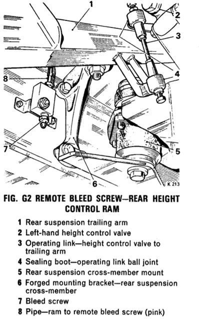
Depressurise the height control rams (see Fig G2) by placing a bleed tube on each ram bleed screw in turn and bleeding off the fluid with the bleed tube immersed in approximately 1" of RR363 brake fluid in a clean container.
After each ram has been depressurised the bleed screws need to be tightened up and the reservoir topped up to replace the fluid that was bled off.
Bleeding procedure for the low pressure master cylinder circuit
Please note that on the rear calipers the position of the high and low pressure bleed screws changed as per diagrams G44 and G45 below. Please confirm which caliper you have as they may have been replaced over time.
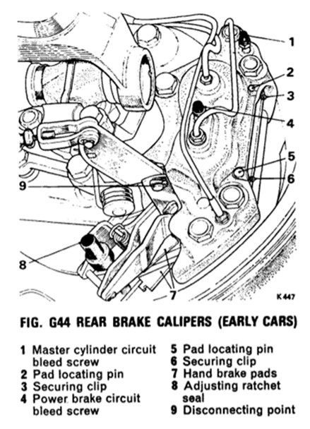
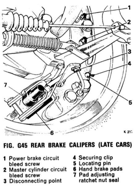
Step 1. Fit a bleed tube (immerse the open end into a container containing about 1" of clean RR363 brake fluid) to the master cylinder bleed screw only on one of the rear calipers. Open the bleed screw wide whilst your assistant presses the brake pedal down quickly and when the pedal is fully down re-tighten the bleed screw. Repeat this operation until all air bubbles cease and then tighten the bleed screw during a downward stroke of the brake pedal i.e. whilst the fluid is flowing into the container.
Step 2. Repeat Step 1 for the opposite rear caliper.
Step 3. After the above has been completed check the reservoir fluid level and top up as required.
Step 4. Start the engine and run for a short period of time at 1000rpm to charge the power system (high pressure) and re-check the reservoir fluid level and replenish as required.
Bleeding procedure for the high pressure (power system) - 2 people required.
Step 1. It is recommended that the gearchange thermal cut-out is removed from the fuse board as a safety precaution. Run the engine for a short time to ensure that the power brake systems are fully charged.
(See Fig M2 and M3 below to identify your thermal cut-out)
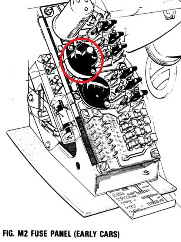
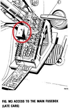
Step 2. Attach a bleed tube (open end immersed in RR363 brake fluid in a suitable clean container) to one of the accumulators and carefully slacken off the bleed screw just enough for the fluid to flow and leave open until all air bubbles have stopped and allow 15 seconds after they have stopped before re-tightening the bleed screw. Check fluid level in reservoir and top up if required to upper level.
Step 3. Repeat Step 2 for the other accumulator. Top up fluid reservoir to upper level if required.
Step 4. Attach a bleed tube (open end immersed in clean fluid in a suitable container) to any of the front brake calipers, then, whilst the second operator lightly depresses the brake pedal and holds it under pressure (between 20lbs and 25lbs), open the bleed screw and bleed until all air bubbles have ceased and leave open for a further 15 seconds after and then tighten the bleed screw.
Step 5. Attach a bleed tube to either rear brake caliper on the power circuit bleed screw (bleed screw No.4 on Fig G44 or No.1 on Fig G45) and whilst the second operator depresses the brake pedal halfway, open the bleed screw a small amount until fluid appears in the tube. When the fluid is free of air bubbles open the bleed screw a little further and allow to bleed for a further 15 seconds and re-tighten the bleed screw and allow the brake pedal to return to its off position.
Step 6. Repeat Step 5 for the opposite rear caliper.
Please note: The later cars with the pressure limiting G Valve in the power brake circuit (see Fig G1 below) require care when opening the above bleed screws because if they are opened too wide then the ball in the G Valve will be forced against its seat and stop the flow of fluid. If this happens then close the bleed screw and release the brake pedal and repeat the procedure, BUT WITH CARE.
Step 7. The engine now needs to be run for approximately 2 minutes after the last caliper has been bled and before proceeding to Steps 8 - 13.
Step 8. Bleeding the rear height control rams, requires the weight of 1 person in the boot (trunk) as the rear suspension needs to be compressed during this operation. The brake pedal does not need to be depressed but the system needs to be operating on fast height control.
Step 9. Attach the bleed tube to either of the rear height control rams bleed screw (see Fig G2) and open the bleed screw a small amount to allow fluid to flow through the tube and leave open until all air bubbles cease, keep the bleed screw open for 15 seconds after the bubbles have ceased and then re-tighten the bleed screw.
Step 10. Repeat Step 9 for the opposite height control ram.
Front height control – only if fitted and operational
Step 11. Weight the front of the car sufficiently to compress the suspension.
Step 12. Attach a bleed tube to a bleed screw on either front height control ram ‘T’ shaped casting on the front damper top plate and open a small amount to allow fluid to flow and leave open until all air bubbles cease and leave open for a further 15 seconds before re-tightening the bleed screw.
Step 13. Repeat Step 12 on the opposite side.
Check fluid levels and test drive the car.
Diagram G1 below shows the flow of fluid through the hydraulic system. Early cars incorporated the G valve in the low pressure system, whilst later cars incorporated the G Valve in the high pressure system. Both diagrams show the early front height control system but this may have been disconnected or deleted.
