Suitable for Rolls-Royce & Bentley models between:
- 1965-1980 (From VIN 11800 onwards)
- 1980-2003 (From VIN 1001 up to 27798)
This information is taken from Workshop Manual TSD2476, Section H.
1. Apply the hand brake and chock the rear wheels.
2. Remove the gear range selector thermal cut-out, as described in Chapter M - Electrical System.
3. Carefully position a jack beneath the front lower triangle lever pivot points at the centre of the car; a hardwood block should be placed between the jack head and the pivot points before raising the car.
4. Remove the combined wheel disclhub cap, and slacken the road wheel nuts, but do not remove the road wheel.
5. Raise the car and place suitable blocks to support the sill boards (RH 7820) beneath the body sills. In addition, place supports beneath the outer ends of the front lower triangle levers.
6. Remove the wheel nuts and road wheel(s).
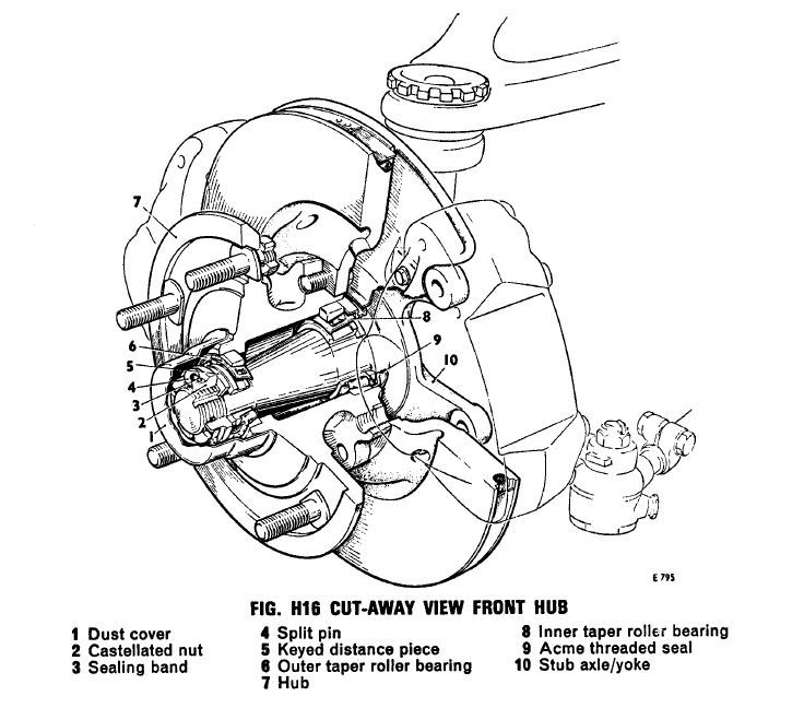
7. Using a screwdriver inserted between the lip of the hub dust cover and the hub flange, prise off the dust cover. Care must be taken when removing the dust cover to avoid damaging the earthing contact inside the cover.
8. Remove the sealing band split pin, castellated nut and keyed washer from the stub axle. It will be necessary to break the sealing band in order to remove it from the split pin.
Note: The right-hand stub axle has right-hand threads, the left-hand stub axle left-hand threads.
9. The brake disc is secured to the hub by setscrews, therefore it will be necessary to remove the brake calipers in order to withdraw the hub from the stub axle. (See Chapter G - Hydraulic System).
10. Withdraw the hub from the stub axle complete with bearings and grease retainer.
11. Retain the chamfered distance piece.
12. Place the hub on a suitable working surface; inspect the brake disc and pads of the brake calipers for wear or scoring.
13. Ensure that the brake disc setscrews are torque tightened to the correct figure (see Chapter P - Torque Tightening Figures).

